#mathjoke
In the first of our promised tech-heavy safety related articles, we will discuss proper harness installation. Just as a warning (or perhaps an apology), the WavingBearFlag.com staff all have engineering backgrounds. (Although only one of us is actually an engineer. #theLEAgue!) Throughout this article and those to follow, you will need at least a little knowledge about mathematics, geometry, engineering mechanics, mechanics of materials , quantum mechanics, haberdashery, phrenology, and basket weaving… I may have gotten a bit carried away there, but you get the idea. We will attempt to give a simplified primer on the physical phenomena involved with each article at the beginning so anyone without a technical background can hopefully understand what we are on about. We are not here to confuse anyone or to get into lengthy debates about physics and we are certainly not the absolute final authority on any subject we present. We only want to arm our readers with some tools and knowledge to ask the right questions when they go to their builder or safety gear supplier so you can be sure that you get the right gear for your situation and that it is installed correctly. If you find fault with our materials, do please let us know. We will always strive to present the best and most accurate information we can find!
Primer
Lets begin with a discussion of Statics. Statics is a subset of engineering mechanics that is concerned with the distribution of forces through rigid bodies at rest.
Having fun yet?
To simplify, imagine a cable suspended from the ceiling. From that cable, we hang a 100# weight. (A note for pedants: Yes, I’m using the terms weight and pounds. I know the mass and weight and force are not all necessarily interchangeable. Don’t like it? Extoll the virtues of the kilonewton and *shudder* the slug on your own website. #MultiplyByG)
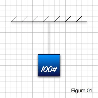
For the purposes of statics, the ceiling and the cable are both ‘rigid bodies’. That means the ceiling doesn’t sag and the cable doesn’t stretch. Consideration of those factors would be handled in the next step of design and we won’t concern ourselves with them here… though just wait until my rant about CrMo! Also, for the purposes of statics, we will say that the weight isn’t swinging around or spinning or bouncing up and down. It is ‘at rest’.
One of the key principles of statics is that all forces acting on a rigid body at rest must be equal and opposite, otherwise the rigid body wouldn’t be at rest. It would be moving in the direction of some unbalanced force. For our first example, that means that if you have 100# pulling down, the cable has 100# of tension acting on it, and the attachment point at the ceiling is resisting the downward force with a 100# vertical force.
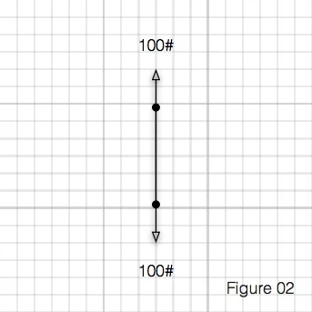
Pretty simple stuff.
Lets make it a bit more complicated.
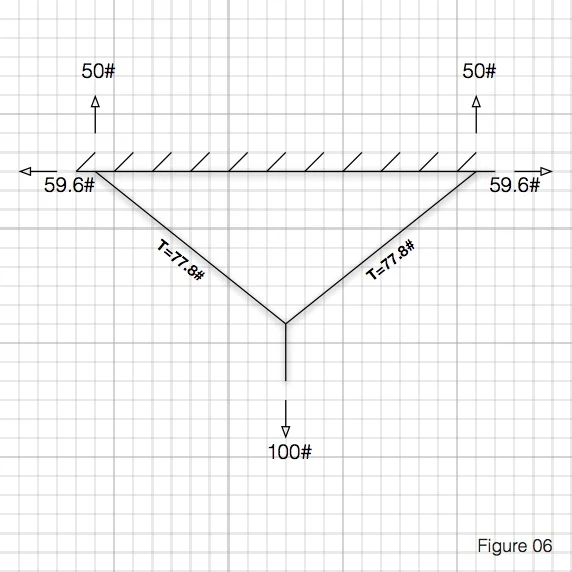
Lets say that we have a pulley and cable arranged as below.
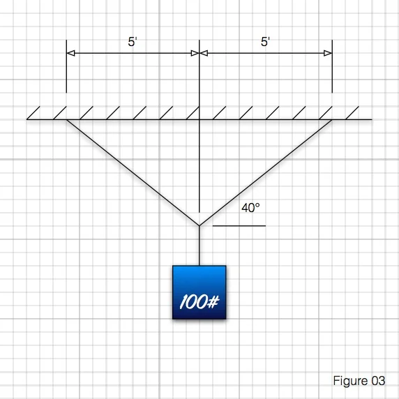
We have the same 100# pulling straight down, but now that 100# must be distributed into each side of the cable and into the two ceiling mounts. For slightly more complex mathematical reasons that I want to get into here and due to the fact that the load is centered between the supports, each ceiling bracket resists the load with 50# of vertical upward force each, but what about the horizontal resisting forces? The bad news? These reactions certainly exist, but finding their values isn’t as intuitive. The good news? Geometry time!
First, we can find the tension in the cables. We know at the supports, there is a 50# force acting vertically upward. That means that the cable on each side must be exerting a 50# force acting downward. Since a cable can only carry a force along its length, there must be a horizontal force as well. As is works out, the relationship between the forces is the same as the relationship between the horizontal and vertical distances travelled by the cable.
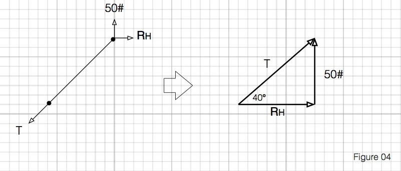
Using the trigonometric functions (huzzah!) that we all pretended to learn in 10th grade, we can find the tension (T) in the cable and also the horizontal force at the ceiling.

So, the whole system looks like:
Since the horizontal and tension forces vary with the angle, you can see that any change in the angle will affect those forces also. More on this later.
Harness Angles
Race harnesses are nylon belts that restrain a driver or passenger in a vehicle and transmit forces exerted by the driver or passenger in an impact through the belts in tension (you can’t really compress a belt along its length. Give Euler a google if you want to know why) and into the structure of the car. Nylon belts do stretch a bit, but we’ll leave that to the manufacturers and say, for the purposes of this discussion, that they act as ‘rigid bodies’. Also, just because there are lots of things moving in an undesirable fashion during an accident doesn't mean that properly installed and worn belts won't stay basically where they are meant to, so we can say that they are ‘at rest’. Since we can use our newfound geometry skills on the belt system, it becomes clear that belt angles change the forces inside the belts. As you’ll soon see, they also change the forces exerted on your body.
So, what does this mean for you? It means that you can buy a very expensive set of belts, install them with all the right hardware, double check all of your connection points, but if you don’t install them at the correct angles, you can turn your belts into force MULTIPLIERS on certain parts of your body! Most notably, your spine.
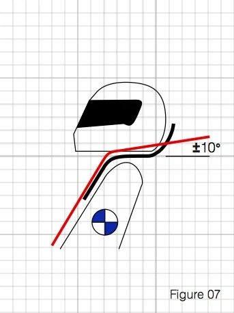
Typically, belt manufacturers tell you to mount the shoulder belts not more than 20* from horizontal behind the seat.
This is one of the most ignored and probably misunderstood details of belt mounting. I can’t tell you how often I’ve seen belts that turn down at an extreme angle from the driver’s shoulder. This seems to give people a sense of security. On the surface, I suppose it does seem to make some sense. When you strap the belts down in this arrangement, you are pushed into the seat. You feel like a part of the car. The problem is, you have just set yourself up for massive spinal compression in an accident.
Lets take a moment to draw up what is really happening with your shoulder harnesses in an accident and apply the rules of statics.
In a front collision, the car slows rapidly. Newton tells us that a body in motion (in this case YOUR body) tends to stay in motion unless acted on by an outside force. The shoulder harness provides this outside force… at least for the top half of your body. More on the rest of you later.
So the deceleration that you experience applies a forward force and throws you into the belts.
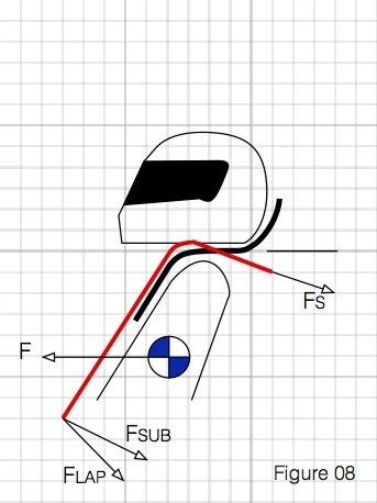
This force is distributed through the shoulder, lap, and antisubmarine belts and into the car’s structure. If we draw a free body diagram (that’s a fancy-pants engineering term for a sketch showing all the forces) at the driver’s shoulder, you get the following:
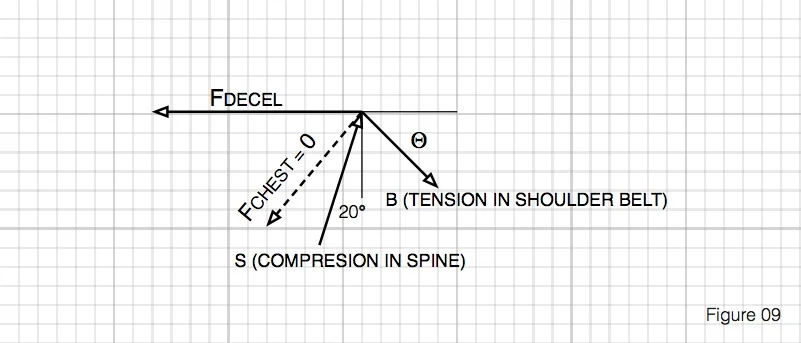
When you consider all the forces that are acting at the driver’s shoulder, you see that the deceleration force is acting horizontally forward (we’ll assume a front end collision), the force in the piece of the shoulder belt that goes over the driver’s chest goes to zero since Mr. Euler won’t let it take a compression force (This assumption is not entirely accurate, but without a detailed analysis of frictional forces, deflections, and other data that I do not have at my disposal, we will model the shoulder as a pin where all the forces act together. Assuming that there would be an additional tension force through the forward section of the shoulder belt leading to the cam lock would only serve to amplify the affect we will observe, so the method here should be conservative.), and the force in the shoulder belt going from the driver to the car is tension along the length of the belt. If we consider the spine to be a rigid link from the driver’s shoulder to the bottom of the seat at some angle (I’ve chosen 20* since that it pretty common for most full bodied cars), there will also be some force acting along its length.
The actual magnitude of the deceleration force is the function of many, many variables, but one we are most concerned with is the g-loading on the driver’s body. This is a convenient unit of acceleration as a multiple of the normal acceleration due to gravity. (Yes, yes. I know, only on Earth, near sea level, during a full moon, when the bells ring… Are you still here? Shouldn’t you be huddled in your basement somewhere composing a snarky blog post about my last messy treatment of physics vocabulary?) See http://www.formula1-dictionary.net/g_force.html for a good explanation. That said, whatever the force caused by the impact is, it will likely be substantial. Since we know that the belt angle affects the belt tension and reaction forces from our earlier work, lets take a look at how varying the shoulder belt angle from 0* to 60* affects the belt tension and spinal compression forces. For the sake of nice round numbers in this example, we’ll say that the deceleration force is 1000 units.
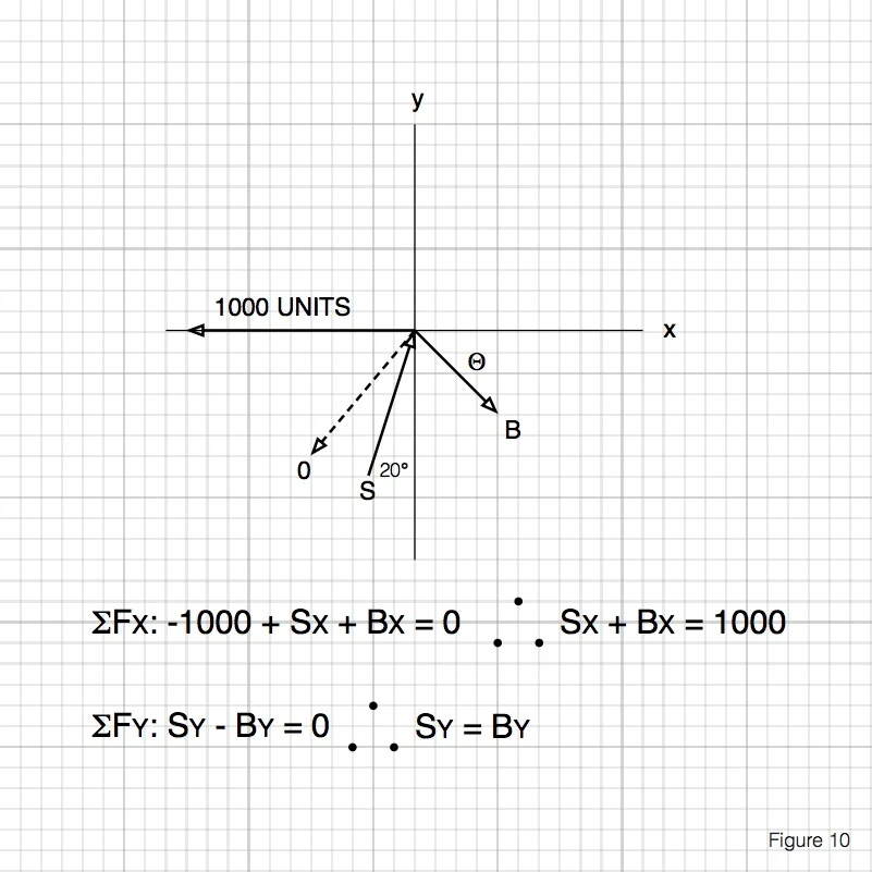
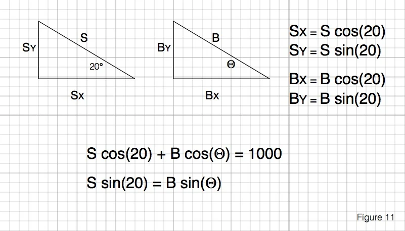
Don’t be intimidated by the math here. It’s actually pretty simple stuff. As we said before, all the forces must equal zero if nothing is moving, so I’ve totaled up the forces in each direction. Sx and Bx are the horizontal components of the belt and spine forces, and Sy and By are the vertical components. After a bit of algebra, you can see that the vertical component of the compression force acting on the spine is equal to the vertical component of the tensile force acting on the shoulder belt. This is important! Without continuing any further, it becomes apparent that a more extreme angle in the shoulder belt means more compression force in the driver’s spine in an impact. Lets carry it a bit farther and see how much the angle will amplify that force.
Still awake? Good. I’ve tabulated all the forces and their components for our range of angles. As you can see below, even a small downward angle on the shoulder belts can cause a significant increase in the forces that the spine can see in an impact!
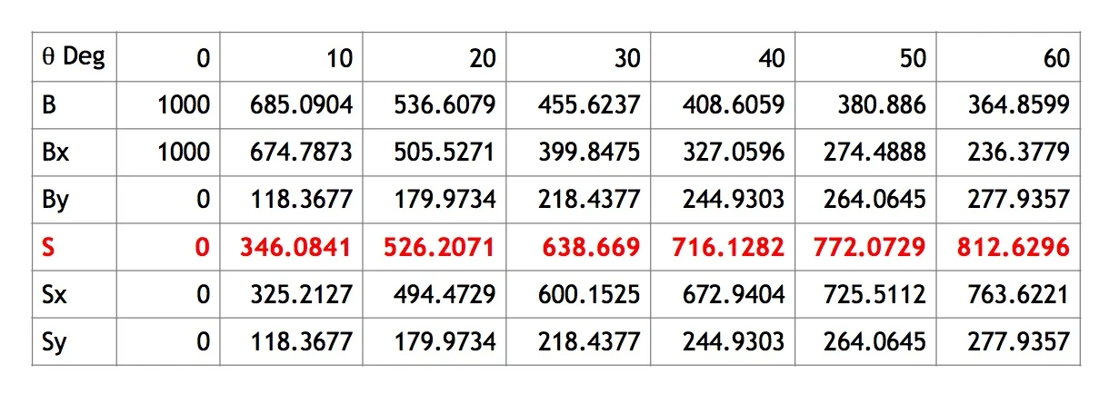
At a harness belt angle of 60* down, the compression force on the spine can be as much as 81% of the deceleration force acting at the shoulders!
Seat Backs
So, now it is clear why the belt manufacturers suggest a flat or very nearly flat arrangement for the aft section of the shoulder harness. The next obvious question is: how can we ensure that we get the appropriate angle? To answer this, lets take it step by step from the top of the driver’s shoulder to the ultimate attachment point.
The first potential area for interference is the seat back. The center of the holes in the seat back should align with the shoulder belts when the driver is strapped in at the installed angle of the seat. The harness should not ‘break over’ the hole in the seat for any reason. Ideally, the shoulder belts should not touch the seat opening at all. If routed incorrectly, the belt will try to exert a force into the seat opening in an impact. This changes the angle of the belt and, as we have seen, changes the forces acting on the body. It can also chafe the belt causing damage, cause damage to the seat and, in extreme instances, it could cause failure of the belt in an impact.
Furthermore, if using harnesses with a factory seat (which I don’t recommend for reasons that we will cover in a future article), make sure that the shoulder belts can route either around or between the headrest supports and still maintain the correct geometry. You should not use a seat without a headrest and you should never allow the shoulder belts to pass around the sides of the headrest.
Next in the chain is the span between the seatback and the harness connection point. This is typically to a harness bar. Ideally, this will be integrated into a full roll cage, but a less complete structure may be adequate for proper harness installation. Look for a future article on harness bars. The shoulder harnesses should route rearward parallel to the axis of the car. The distance between the shoulder and the attachment point should be as short as is practical. Some manufacturers allow long distances between the shoulder and the attachment point and may recommend narrowing or even crisscrossing the belts in this arrangement. We don’t like this method if it can be avoided. Remember that even though we modelled the belts as ‘rigid bodies’ for the purposes of our analysis, they do stretch when loaded. To minimize the risk of a piece of the system moving is an undesirable fashion, we feel that the belt lengths should be kept as short as possible.
Finally, is the attachment point. Since the rules on this apply to all belt anchor locations, we’ll consider them in our next article when we look at lap and anti-submarine belts.
Again, this is not intended as an all-inclusive guide, but we hope that you can use the principles presented here when you begin shopping for safety gear and, perhaps just as importantly, when you begin your installation. All questions and comments (not related to gravitational acceleration) are always welcomed.